Building Without Support
September 30, 2021 | Reading time: 5 min
Building without supports or with a minimum of supports is a hot topic in metal powder bed fusion. The reason is apparent: Cost reduction. The number of supports impacts not only post-processing but also build-time and material consumption.
A Step-by-Step Guide
To structure the article, I will use the Design Thinking approach. I would first of all like to emphasize the design aspect.
Emphasize

Define
In order to avoid supports on your application we should ask ourselves about their purpose. The three reasons for support are:
- Heat transfer
- Residual stress
- Recoater forces
Heat transfer: Due to the reduced heat conductivity of powder compared to solid material, the energy input has to be adapted in overhanging areas. As I have shown in the previous article, the heat transfer topic can be mitigated with an adapted DownSkin exposure strategy and optimized process parameters.

Residual stress: Since metal powder bed fusion is typically what we call a cold process, residual stress is the result of the laws of physics. Stress occurs because of the temperature gradient due to locally concentrated energy input as well as the temperature difference between layers that just solidified and already cooled down ones below them. Material shrinkage is also partially restrained by previously solidified material and can lead to distortion.
Rather than working on the cause of residual stress by increasing the build temperature (with the drawback of increased oxygen pickup) or with special scan strategies (with drawbacks on mechanical properties or productivity) it is easier to compensate for the arising effects. Solutions are pre-deformation or, if possible, designs that are less prone to deformation. Below you can see two examples simulated with Amphyon from Additive Works: A flat plate and an upside down cone. Both parts have similar dimensions (50 mm diameter vs. 50 x 50 mm). You can clearly see that the cone shows less deformation because of its geometry. It is starting in one point and then continuously growing in z-direction. Also the circular shape in x-y layers acts self-stabilizing.
Recoater forces: During recoating, forces are acting on the part while spreading the powder. If a part is not connected to the baseplate, it will be wiped away by the recoater. Depending on the geometry and process, these forces will be bigger or smaller. Using a soft-recoater is an option especially for filigree parts but only a hard recoater can guarantee a constant layer thickness. Experience tells: If you can build it with a hard-recoater, you easily can build it with a soft-recoater. This is why the following trial has been done with a hard recoater (HSS blade).
Ideate
Typical solutions to reduce the effect of recoater forces are for example prop supports, which are frequently used for tall tensile bars to increase the stability of print jobs by reducing vibration of the tensile bars during recoating. If we further develop the concept of prop supports, we can use a shell to protect and stabilize a part. Thereby, no connection to the baseplate would be required.
To start with a simple example, we can start with the cones. A simple Boolean with a clearance of 0.2 mm will provide a gap that is big enough to prevent from fusion of part and shell.

Prototype
The cones have been built on an EOS M 290 in EOS Titanium Ti64 and were easily removable by hand.
One could argue that the volume of the shell is bigger than the volume of the part. Therefore, further optimization to find the most beneficial setup is required. At first, you do not have to enfold the whole part but only a certain area in the beginning. The friction between part and shell should be sufficient to hold it in place even for tall parts. Another idea is to stack parts and us the preceding one as a shell for the next part.

Test
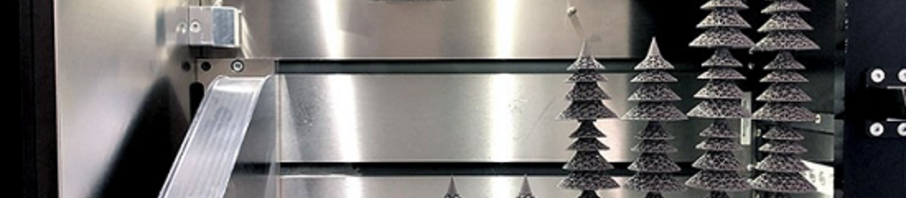
Let’s move on to a more advanced design and even incorporate stacking. Since Christmas season is coming up, how about a Christmas tree designed with Siemens NX and pimped with nTopology? By turning it upside-down, the tree is self-supporting and the tree trunk can act as a shell for the next tree. You can see a small overlap of 0.1 mm in x-y-direction between the lattice and the solid parts in order to assure a good connection.
For nTopology experts: No, I did not export the lattice as a mesh, this is just for the pictures.

Implementation
My article covered the first five steps from Empathize to Test but Additive Minds can support you with the implementation, too. There are already reat examples out there that use minimal or no support.
Smart Fusion
EOS Smart Fusion is our software innovation to significantly reduce cost, increase efficiency and quality in metal 3D printing. It is available with the EOS Smart Monitoring software plan and requires an OT camera system to enable advanced thermal management. This not only accelerates the additive manufacturing process of metal components, but also optimizes it by reducing support structures.

The Hitchhiker´s Guide to Smart Fusion
Whitepaper
A new level of process monitoring. Discover how real-world applications are created using Smart Fusion and learn about the design guidelines that must be considered. Download the whitepaper on "Smart Fusion" and get deep insights into the new way of process monitoring

The Realities and Benefits of Support-Free Metal 3D Printing
Additive Manufacturing Blog
Support-free 3D metal printing is an attractive proposition. But what does it really mean and why is it so appealing? Learn what support-free printing is, whether it’s actually possible and what benefits it can bring.

