
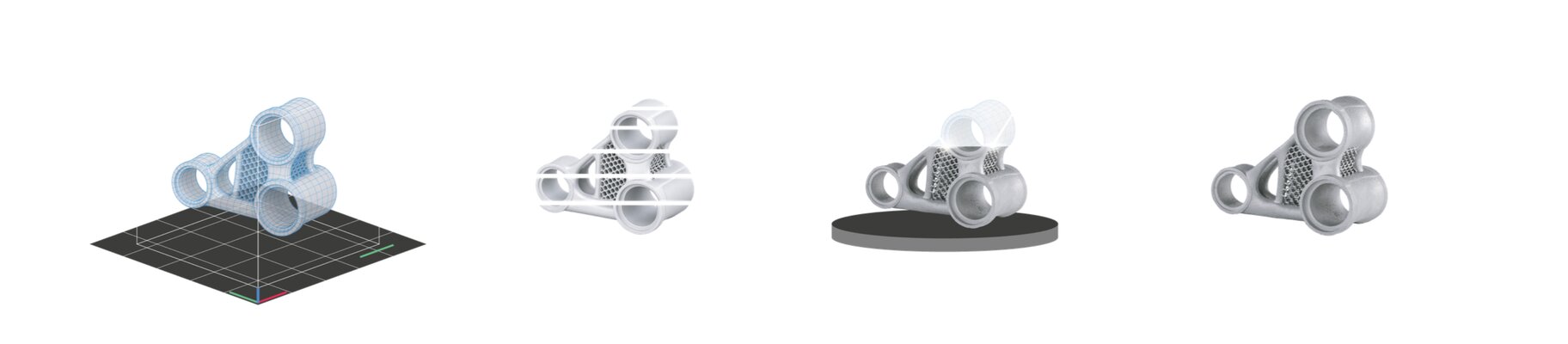
How To Make a 3D Print File
12 October, 2026 | Reading time: 5 min
Creating a 3D print file is the foundational step of any additive manufacturing project. Whether the goal is a simple prototype or a complex functional component, the path from digital concept to physical part always runs through one place: a properly prepared 3D design.
This guide walks through the full process - what a 3D printable model actually is, which file type to choose, the step-by-step workflow for creating one, and the design rules that separate a printable model from one that fails on the build plate.
What Is a 3D Print File?
A 3D print file is a digital blueprint that tells a 3D printer exactly what to build. Unlike a 2D image, it contains three-dimensional surface geometry data - information describing the shape, structure, and spatial dimensions of an object.
Most 3D-printed parts start life as a CAD model, built using a specialized 3D modeling program. Before that model can be sent to a printer, it needs to be converted into a format that slicing software can read and translate into layer-by-layer build instructions. A high-quality 3D model at this stage directly determines whether the final printed part matches its intended specifications.
What Is an STL File and Why Is It Used?
The STL file is the most widely recognized format in 3D printing. STL stands for stereolithography, and it works by describing a model's surface geometry as a mesh of triangles - a raw, unstructured triangulated surface with no color, texture, or material information attached.
The STL format earned its status as the industry standard for a straightforward reason: virtually every slicing software on the market supports it. That universality makes it the default choice for moving from design to 3D-printed parts, regardless of hardware brand or material type.

Common File Types for 3D Printing
The STL file format is the starting point, but it's not the only option. Depending on project complexity and workflow requirements, other formats may be a better fit.
| Format | Best for | Supports Color/Texture | Slicer Compatibility |
| STL | General-purpose 3D printing process | No | Universal |
| OBJ | Artistic and visual designs requiring color/texture data | Yes | Broad |
| 3MF | Modern workflows; packages complex designs, 3D printing materials, and print settings in one file | Yes | Growing |
| STEP | Professional CAD-to-CAD exchange; parametric solid geometry | No | Limited (improving) |
For most hobbyists and early-stage product designers, STL or 3MF will cover the majority of use cases. Organizations working in professional additive manufacturing environments may encounter STEP files when integrating with broader engineering systems.
Step-by-Step: How To Create a 3D Print File
The journey from high quality 3D models to clean prints follows a predictable sequence. Working through each step methodically reduces the risk of print failures and rework.
Step 1 - Conceptualization: Define the purpose and constraints of the part. Sketch basic shapes, note critical dimensions, and consider how the object will be used or assembled.
Step 2 - 3D Modeling: Open a CAD program and build the digital geometry. This is where the actual design work happens - constructing surfaces, adding features, and refining the shape to match the concept.
Step 3 - Exporting: Save the completed design in a compatible 3D file format. For most workflows, this means exporting as an STL or 3MF file. Check that the export resolution is high enough to capture fine details without creating an unmanageably large file.
Step 4 - Slicing: Import the exported file into slicing software. The slicer translates the 3D geometry into horizontal layers and generates the machine-readable instructions the printer needs.
Step 5 - Setting Parameters: Configure print settings within the slicer: layer height, print speed, support structures, and material-specific profiles. These choices directly affect print quality, strength, and material consumption.
Step 6 - Transfer: Export the final G-code file and send it to the printer - via USB, SD card, or a networked workflow. The machine reads the G-code and begins building the part layer by layer.
Choosing the Right CAD Software
The right 3D modeling software depends on the user's experience level and the nature of the part being designed.
- Parametric Modeling (e.g., SOLIDWORKS, Autodesk Inventor): Dimensions and features are driven by parameters, making it ideal for mechanical parts where precise tolerances mratter. Changes propagate automatically through the model.
- Direct Modeling (e.g., Autodesk Fusion 360's sculpting environment, Blender): Better suited for organic, fluid shapes and artistic designs where flexibility matters more than dimensional precision.
- Slicer Programs (e.g., EOSPRINT, PrusaSlicer, Ultimaker Cura, Simplify3D): Not design tools, but essential for the final preparation stage - translating a finished 3D model into print-ready instructions.

Beginner-Friendly 3D Modeling Tools
Extensive CAD experience is not a prerequisite for creating 3D printable files. Several tools are specifically built for users who are new to 3D modeling:
- Tinkercad: A browser-based tool that uses simple shape operations - no installation required, and the learning curve is shallow enough for complete beginners.
- SketchUp: Well-suited for architectural and geometric designs; the interface is intuitive for users comfortable with spatial thinking.
- Fusion 360: Offers a free trial and a clear upgrade path to professional parametric features as skills develop.
- SelfCAD: Combines modeling and slicing in a single interface, which simplifies the workflow for users who want fewer tools to manage.
Design Rules for 3D Printable
A model that looks correct on screen won't always print correctly in the physical world. Four design rules have an outsized impact - and two of them depend on whether you're printing in polymer or metal.
Wall Thickness: Walls must support the layers above them. As a rule of thumb, stay above 1–2 mm. But the real floor depends on the process - and, for metal, on the material and what the part has to do. Standard polymer SLS holds detail down to ~0.7 mm. Metal has no single minimum: It’s material-dependent and hinges on whether the part needs to be pressure-tight. Walls can be printed as thin as 0.1 mm - in nickel-based alloys like Inconel, for example. However, at that thickness, they won’t be pressure-tight, which is fine in applications that don’t require it, such as honeycomb seals. Where repeatable pressure-tightness matters, nickel-based materials need roughly 0.5-0.7 mm, and aluminum somewhat more. EOS's Fine Detail Resolution (FDR) technology pushes polymer walls to just 0.22 mm - using a CO laser with half the beam diameter of conventional SLS - for filigree parts like filter units, plugs or microwave components.
Support Structures (process-dependent): This is where polymer and metal diverge completely. In polymer powder-bed printing, the surrounding unfused powder supports the part, so overhangs and undercuts print freely with no supports. Metal printing requires supports - both to stop the denser melted material from sinking and to anchor the part against thermal warping.
Manifold Geometry: The model's surface must be watertight - no holes, open edges, or non-manifold geometry - regardless of material. Most slicers can't process a mesh that isn't fully closed.
Orientation and Tolerances. How a part sits on the build plate affects surface quality and support needs. And because materials shrink as they cool, any dimension that mates with another component should account for material-specific shrinkage.
Start or Reignite Your Additive Journey With EOS
Learning how to make a 3D print file is the first step toward mastering additive manufacturing. With the right software tools and a solid grasp of design rules, anyone can move from a concept to a printable model - and modern tools have made that starting point more accessible than at any point in the technology's history.
For organizations looking to move beyond prototyping and into production-grade additive manufacturing, the variables multiply: material selection, build parameter optimization, quality assurance, and process repeatability all become factors. That's where expert guidance makes the difference.
Book a consultation to discuss professional 3D printing solutions with the EOS team - or visit the EOS Store to explore specialized software, materials, and systems built for serious additive manufacturing applications.


