
Reimagining 3D Printing with an Innovative Exposure Strategy
June 28, 2022 | Reading time: 7 min
At EOS, we are always exploring new technologies and methods to enhance the 3D printing process. Our team has developed an exciting new strategy for laser exposure that results in better quality production and a reduction in energy expenditure.
A new strategy for laser exposure
At EOS, we are always exploring new technologies and methods to enhance the 3D printing process. Our team has developed an exciting new strategy for laser exposure that results in better quality production and a reduction in energy expenditure.
Why is quality assurance such a concern?
A key benefit to 3D printing over traditional manufacturing methods is its efficiency. But, as with any relatively new technology, there is still plenty of opportunity for advancement. At EOS we are always working to refine and improve the additive manufacturing (AM) process. In our continued efforts to advance 3D printing technology and techniques, we have developed a new exposure strategy method that yields excellent results against the previously considered best practice.
In this article, we’ll take you through the commonly used process of 3D laser printing, the challenges it presents, and the findings of our research to tackle those problems, culminating in the new methodology: Laser Center Depending exposure Strategy (LCDS). Read on to see how a seemingly incremental adjustment can result in significant changes for additive manufacturing.

How LPBF 3D printing works
The principle of additive manufacturing is characterized by its layer-by-layer structure. The build starts with a 3D generated model (CAD), which is sliced into many thin layers and sent to the AM machine (the 3D printer). In the printer, a thin layer of material powder is applied to the build platform and a powerful laser beam melts the powder at specific locations dictated by the computer-generated design data (the CAD model). The build platform is then lowered by a job-specific height and another layer of powder is applied to the build platform. The fresh layer of material is melted again, connecting it with the layer below. These steps are repeated until the final part is realized.
The highly accurate lasers used in the printer move across the powder bed in a prescribed pattern, only firing at the necessary moments to form the digitally designed object. As each thin layer of perfectly even powder is added, the lasers repeat the same travel pattern above the bed.
A team of EOS metal process engineers have conducted a series of experiments to establish an alternative way to program laser allocation and movement, which increases accuracy and build quality. Before exploring this new method, however, it’s important to understand how additive manufacturing lasers currently operate.

The current strategy: DMLS
DLMS technology — also known as Selective Laser Melting (SLM), Laser Powder Bed Fusion (LPBF) or Laser Metal Fusion (LMF) — utilizes a consistent travel pattern for the 3D printing lasers. This pattern is known as the exposure strategy. It moves from one end of the powder bed to the other (known as the stripe direction), snaking left and right in an alternating succession of passes over the build platform (these are the scan vectors). The lasers fire on each pass, regardless of direction, with the aim of timeliness and efficiency.
Much like a conventional paper printer, the lasers don’t need to return to one side of the build platform — the “margin”, as it would be considered on paper — before completing another scan vector. This saves time in the printing process, but it does also present some potential problems.

Spatter formation
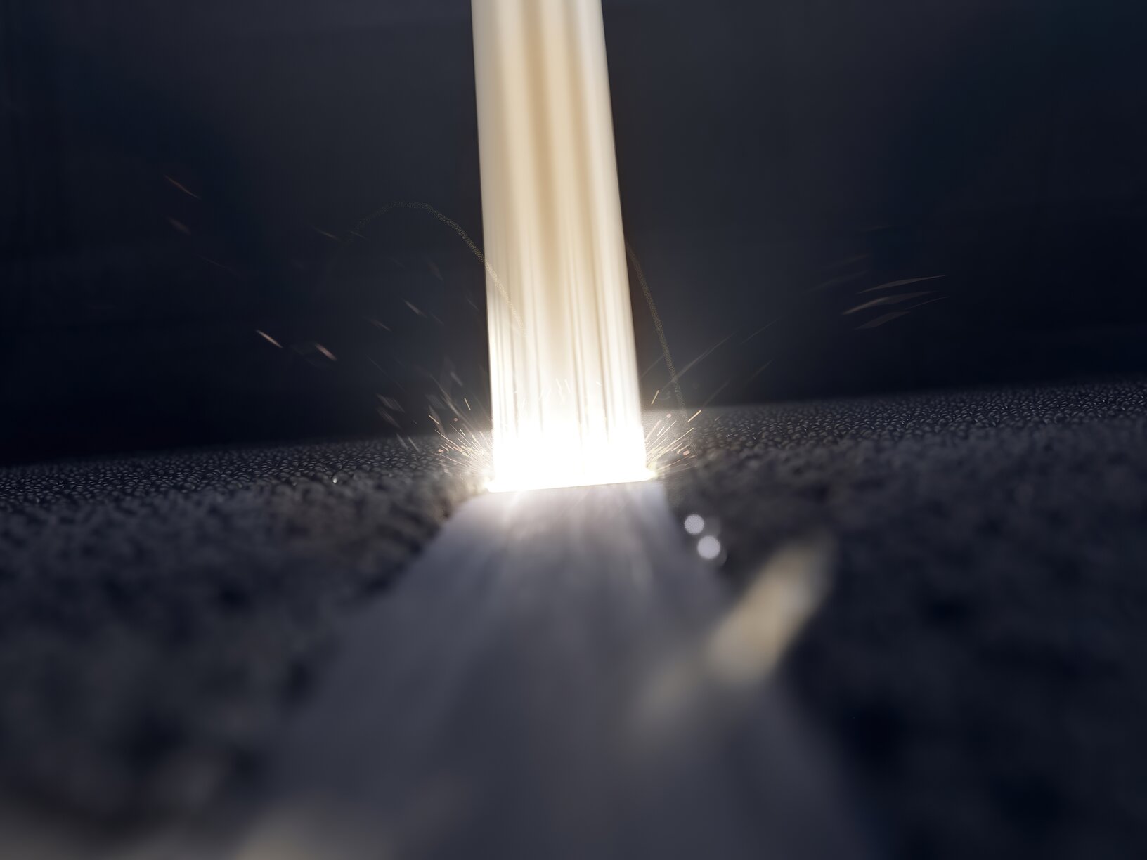
When the lasers hit the powder bed, they sinter the material to form a solid object. However, due to the high energy input and the movement of the lasers, some powder particles are deflected away from the impact point. These particles are also known as spatter. Much like how grains of sand are pushed away from where a ball lands, these particles travel in whichever direction is dictated by the angle of impact.
During the exposure process, the lasers move in multiple directions and various angles relative to the powder bed. Depending on the direction of the laser movement, a different amount of spatter is ejected/deflected from the process location. The result is that the powder particles are deflected away in different directions, causing uneven build-up of powder in random locations.
Defects in the layers
Using alternating scan vectors means that spatter will potentially land anywhere on the build platform, including areas which are yet to be sintered. This means that the perfectly even surface of the powder bed has been compromised and the areas subsequently hit by the lasers will potentially be uneven. The amount of spatter formation is also important because a greater amount of spatter means less material left to form the intended resulting solid surface.
The result will be tiny imperfections in each layer, where too much or too little powder was present at certain points of sintering. This leads to the subsequent layer of powder being uneven as it has to “fill in the gaps” where the preceding layer hasn’t formed evenly, resulting in points where one layer is not properly connected to the previous one. This creates defects and weaknesses in the final product.
The solution: Laser Center Depending exposure Strategy (LCDS)
Through extensive experimentation, our team has established that using alternating scan vectors and stripes isn’t the most effective strategy for laser sintering. The team isolated small cross-sectional areas of the build platform and tested different combinations of stripe directions and unidirectional scan vectors for each laser center (the positioning of the laser above the platform). Specific combinations yielded higher quality results than others, but allowed the team to identify which are optimum for the corresponding laser center.
The team concluded that using exposure patterns in which the stripes and unidirectional scan vectors are aligned in a specific way with the appropriate laser center leads to a reduction in imperfections and an increase in the homogeneity of parts across the build platform. The position of the laser center is proposed as the guiding criterion, which is the reason why the strategy is called the "Laser Center Depending Exposure Strategy" (LCDS).
This is most relevant when aiming to create precision parts, like those needed for aeronautical engineering, where the smallest of imperfections can have serious consequences. Excitingly, we have begun to incorporate aspects of our LCDS findings into our 3D printing software to start to bring these quality advantages to users. In time, we intend to implement more of this new method in our products.
Homogeneous Part Properties across the Entire Build Area
Whitepaper
Download the whitepaper "Homogeneous Part Properties across the Entire Build Area" and get deep insight about an innovative exposure strategy for the EOS M 300-4.